4 kW reference
3000 × 1500 mm format briefing

Fiber-laser cell engineering
Start with material, thickness mix, sheet format, and target takt time. Then compare source power, cutting head control, extraction, and automation as one operating system.
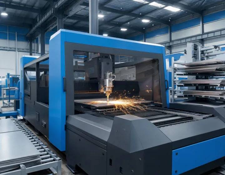
3000 × 1500 mm format briefing
Alloy and assist-gas trial required
Two-column comparison
These are planning checkpoints rather than guaranteed outcomes. Final capability depends on alloy, surface condition, nozzle, gas purity, focus calibration, nesting, and acceptance criteria.
| Review point | 4 kW production brief | 6 kW production brief |
|---|---|---|
| Reference sheet format | 3000 × 1500 mm | 3000 × 1500 mm |
| Primary decision | Balanced mixed-gauge work | Higher power-density study |
| Required evidence | Cut sample, edge criteria, cycle log | Cut sample, gas use, thermal record |
| Automation gate | Shift mix and unload pattern | Throughput and downstream capacity |
Cell architecture
Coordinate source power, motion, cutting head, extraction, and control software against the actual part family.
Review machines →Define loading, unloading, sorting, buffer logic, and operator access before calculating unattended hours.
Review interfaces →Connect training, nozzle care, optics inspection, preventive tasks, and service records to the uptime plan.
Review services →Acceptance evidence
No anonymous performance promise replaces a part trial. Each record keeps the material certificate, program revision, gas condition, measured cycle, and edge acceptance together.
Background: mixed geometries. Process: lock program revision and nozzle. Result gate: record every cycle and inspect the same edge locations.
Background: repeat brackets. Process: trial each specified gauge and gas setup. Result gate: compare burr, heat tint, and downstream fit.
Background: automation study. Process: include load, cut, unload, and interruption time. Result gate: use observed throughput, not theoretical head speed.

Control points
A measurable next step
We will turn the drawing set, material range, quality limits, and shift target into a documented trial plan.